Day 18:spidev - 辣個 userspace 的驅動程式
如同 I2C 有 i2c-dev 這個揭露給 userspace 的字元驅動程式,SPI 子系統也有一個角色類似的字元驅動程式,那就是 (前幾篇文章多少有提到的) spidev。在 userspace 中對 spidev ,就可以對 SPI 裝置進行輸入輸出。而一些 Raspbery Pi 上常見的 SPI 函式庫,比如說 python 的 spidev.py 函式庫,本質上也是對 spidev 的檔案操作來實作。
關於 spidev 的文件,主要紀錄在核心文件中的 SPI userspace API 中。不過如果需要例子,可以去 linux/tools/spi/spidev_test.c 這個例子看。在 linux/tools 這個資料夾下有一些不同子系統的工具,這個 spidev_test.c 顧名思義功能就是拿來測試 spidev 上掛的不同節點的一個程式。
機制
spidev 掛上去時,他會幫每一個 bus 的每一個 Chip Select 在 /dev/ 下新增名稱具有 spidevM.N 形式的節點,其中 M 是 bus 的編號,N 是那個 bus 之下對應的 Chip Select 編號。比如說 bus 0 的 Chip Select 有 0 跟 1 兩個,所以就會新增 spidev0.0 與 spi0.1 兩個檔裝置節點。這點文件中有說明:
For a SPI device with chipselect C on bus B, you should see:
/dev/spidevB.C … character special device, major number 153 with a dynamically chosen minor device number. This is the node that userspace programs will open, created by “udev” or “mdev”.
而 spidev 這個模組建立的這些節點都是字元驅動程式,所以對這些節點進行檔案操作,就可以對對應的裝置進行輸入輸出。
實驗:Raspberry Pi OS 中的裝置節點
依照文件的描述,去看看 /dev/ 裡面有的 spidev 開頭的裝置:
$ ls /dev/ | grep spidev
就會發現出現了一個 spidev0.1:
$ ls /dev/ | grep spidev
spidev0.1
在前幾天的實驗中,在 Raspberry Pi OS 預設的裝置樹中,因為發現 spi0 中的兩個 Chip Select 都被 spidev 給佔去,所以那時候用 Device Tree Overlay 停用了兩個 Chip Select 的其中一個。所以在這之前,要先去 /boot/config.txt 移除覆蓋上去的部分:
-dtoverlay=arduino-spi
+# dtoverlay=arduino-spi
移除之後重新開機,就會看到兩個 spidev 開頭的裝置:
$ ls /dev/ | grep spidev
spidev0.0
spidev0.1
實驗:Python 中的 spidev 模組
除了這之外,在 SPI 第二天的實驗中,用了 ftrace 去追蹤 python 中的 spidev.py 函式庫。也就是下面這個 python 程式:
import spidev
SPI_BUS = 0
SPI_SS = 0

spi0 = spidev.SpiDev()
spi0.open(SPI_BUS, SPI_SS)
spi0.max_speed_hz = 5000

msg = input("msg> ");
spi0.xfer([ord(c) for c in msg])
假定這個檔案叫做 spidev-example.py,使用 ftrace 去追蹤:
$ sudo trace-cmd record -p function_graph -F python3 spidev-example.py
隨便輸入一個字串,然後請 trace-cmd 去報告:
$ trace-cmd report | less
因為前幾天已經知道:spi_sync 或 spi_async 是 SPI 子系統中傳輸的 API,所以第一件事情就是去找 spi_sync 等函數。然後就發現在某個 ioctl 裡面找到他:
sys_ioctl() {
  ksys_ioctl() {
    __fdget() {
      __fget_light();
    }
    do_vfs_ioctl() {
+     spidev_ioctl() {
        _raw_spin_lock_irq();
        get_device();
        mutex_lock() {
          _cond_resched() {
            rcu_all_qs();
          }
        }
        memdup_user() {
          __kmalloc_track_caller() {
            kmalloc_slab();
            _cond_resched() {
              rcu_all_qs();
            }
            should_failslab();
          }
          arm_copy_from_user();
        }
        __kmalloc() {
          kmalloc_slab();
          _cond_resched() {
            rcu_all_qs();
          }
          should_failslab();
        }
        arm_copy_from_user();
+       spidev_sync() {
          _raw_spin_lock_irq();
+         spi_sync() {
            mutex_lock() {
              _cond_resched() {
                rcu_all_qs();
              }
[...]
那確實這也是用 ioctl 傳輸的。因為從 SPI userspace API 文件中,可以找到以下的敘述:
"Standard read() and write() operations are obviously only half-duplex, and the chipselect is deactivated between those operations. Full-duplex access, and composite operation without chipselect de-activation, is available using the SPI_IOC_MESSAGE(N) request.""
所以要用全雙工模式,就要用 ioctl。而在 linux/tools/spi/ 中的 spidev_test.c 中,可以看到以下的程式碼:
[...]
    ret = ioctl(fd, SPI_IOC_MESSAGE(1), &tr);
    if (ret < 1)
        pabort("can't send spi message");
[...]
所以驗證的 python 的函式庫確實也用到了 spidev 這個裝置。
例子:spidev_test
是 linux/tools/spi/ 底下的工具程式,可以用來操作 spidev 所建立的那些字元驅動程式 (也就是傳輸訊息或讀訊息、調整頻率、調整 CPOL 跟 CPHA 等等)。除了作為使用 spidev 的示範,也可以作為測試與效能分析使用。直接去核心原始碼中的 tools/spi/ 下 make:
$ cd tools/spi/
$ make
之後就會發現裡面有一個 spidev_test 程式。隨便打個選項進去看說明:
$ ./spidev_test -h
./spidev_test: invalid option -- 'h'
Usage: ./spidev_test [-DsbdlHOLC3vpNR24SI]
  -D --device   device to use (default /dev/spidev1.1)
  -s --speed    max speed (Hz)
  -d --delay    delay (usec)
  -b --bpw      bits per word
  -i --input    input data from a file (e.g. "test.bin")
  -o --output   output data to a file (e.g. "results.bin")
  -l --loop     loopback
  -H --cpha     clock phase
  -O --cpol     clock polarity
  -L --lsb      least significant bit first
  -C --cs-high  chip select active high
  -3 --3wire    SI/SO signals shared
  -v --verbose  Verbose (show tx buffer)
  -p            Send data (e.g. "1234\xde\xad")
  -N --no-cs    no chip select
  -R --ready    slave pulls low to pause
  -2 --dual     dual transfer
  -4 --quad     quad transfer
  -S --size     transfer size
  -I --iter     iterations
比如說,假定 test.bin 的內容是長這樣:
$ cat test.bin
spidev_test test
把 Arduino 接上 SPI,並且把 Slave 接到 CE0。並且使用以下的程式接收從 Raspberry Pi 來的傳輸:
#include <SPI.h>
void setup() {
    Serial.begin(9600);
    pinMode(MISO, OUTPUT);
    pinMode(MOSI, INPUT);
    SPI.setClockDivider(SPI_CLOCK_DIV128);
    SPCR |= _BV(SPE);
    SPCR |= _BV(SPIE);
    SPCR &= ~(_BV(MSTR));
}

#define BUF_LEN 128
char buf[BUF_LEN + 1] = {0};
int top = -1;
ISR(SPI_STC_vect)
{
    buf[(++top) % BUF_LEN] = SPDR;
}

void loop() {
    Serial.println(buf);
    delay(1000);
}
打開序列埠,用 400kHz 的頻率,以 test.bin 當輸入,對 spidev0.0 寫入:
$ sudo ./spidev_test -s 400000 -i test.bin -D /dev/spidev0.0
spi mode: 0x4
bits per word: 8
max speed: 400000 Hz (400 KHz)
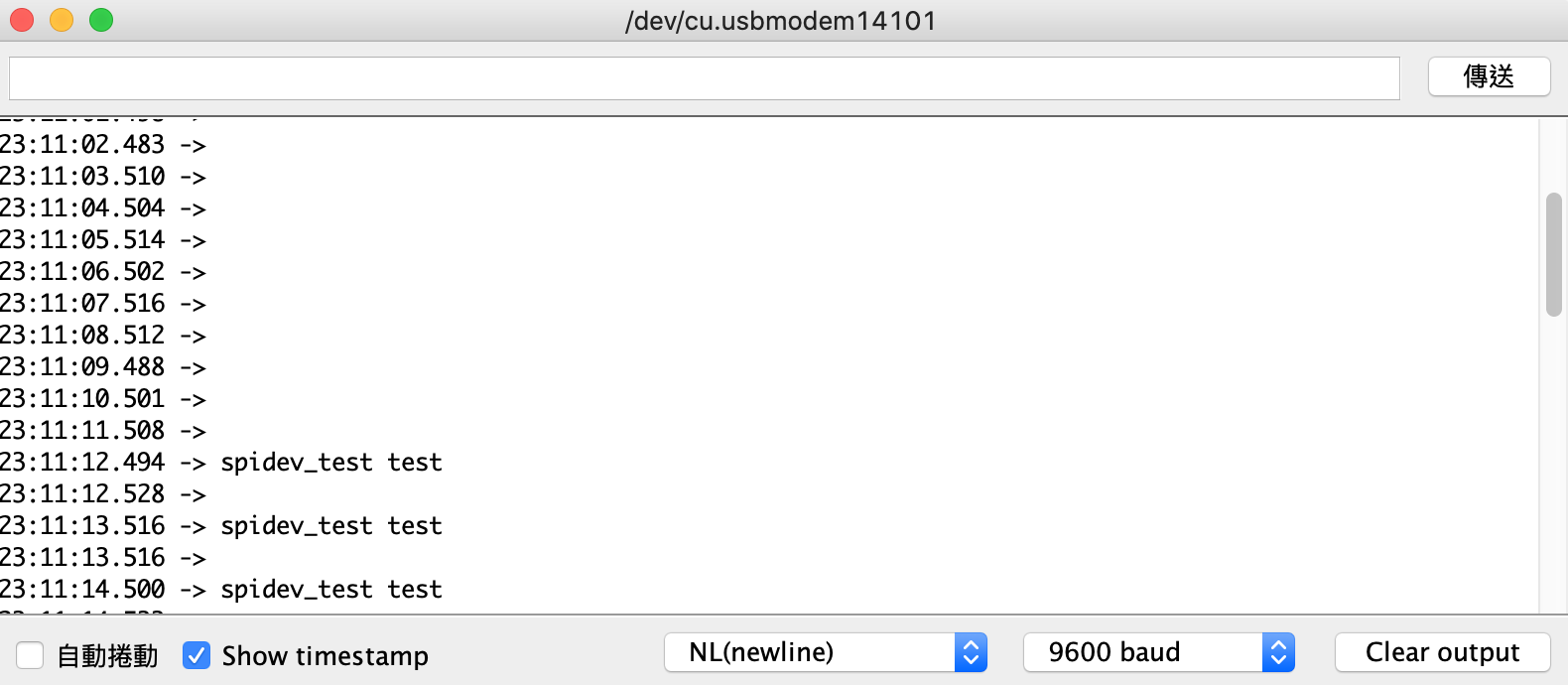
就會發現序列埠出現結果了: